Globe Valves & Control Valves

Precision modulating control of flow and temperature in steam, water, thermal oil and process fluid systems. 2-way and 3-way versions with pneumatic, electric and manual actuation.

Globe valves vs. control valve assemblies

A globe valve uses a plug that moves perpendicular to the seat to control flow — the curved S-shaped flow path through the body inherently causes some pressure drop, but in return provides excellent throttling characteristics and precise control. Globe valves can be operated manually (as precision needle valves, instrument valves or handwheel-operated regulating valves) or fitted with pneumatic, electric or hydraulic actuators to form a complete control valve assembly.

A complete control valve assembly consists of: the valve body (2-way or 3-way globe, cage-guided or plug-guided), the actuator (pneumatic spring-diaphragm, pneumatic cylinder or electric motor), the positioner (electro-pneumatic or digital, receiving 4–20 mA or HART signal from the DCS/PLC) and accessories (limit switches, solenoid pilot valves, air-to-open/close features, handwheel override, air filter regulator).

Roffia distributes control valve assemblies from Spirax Sarco (steam and condensate specialisation) and Danfoss (HVAC and process), as well as complete assemblies with actuators from leading manufacturers. Our technical team can select, specify and supply the complete assembly ready for installation, reducing engineering time.
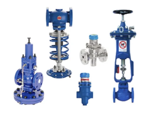
Globe and control valves — Roffia srl

Flow characteristics

  • Linear — equal increments of plug lift give equal increments of flow. Used for constant pressure drop applications and flow control.
  • Equal percentage — each increment of lift gives an equal percentage increase in flow. Used for temperature control and steam service where ΔP varies.
  • Quick-opening — most flow passes in the first portion of travel. Used for on/off and some mixing applications.

Actuator types

  • Spring & diaphragm — standard, inherent fail-safe, 3–15 psi or 0.2–1 bar signal
  • Pneumatic piston — higher thrust, double-acting, for large valves
  • Electric (modulating) — 4–20 mA, 0–10 V, Modbus; no compressed air needed
  • Electro-hydraulic — very high force, fast response for large safety valves

Body materials

  • Cast iron — water, steam to PN 16
  • Carbon steel A216 WCB — steam, process above PN 16
  • Forged steel A105 — high pressure, small sizes
  • Stainless steel CF8M — corrosion resistance, food, pharma
  • Bronze — small sizes, water and steam

Key applications

Steam and condensate systems

Control valves regulate steam flow to shell-and-tube heat exchangers, plate heat exchangers, steam coils and steam-heated jacketed vessels. The valve modulates steam supply to maintain the required process temperature set point. Equal-percentage characteristic and Spirax Sarco body/actuator assemblies are the industry standard for steam duty. See also: energy efficiency in industrial plants.

HVAC and thermal energy systems

In HVAC, 2-way and 3-way control valves (typically DN 15–100) with electric actuators control hot-water and chilled-water flow to fan coils, AHUs and radiant systems. Variable-flow systems use 2-way valves; constant-flow primary circuits with variable secondary use 3-way diverting valves. Danfoss AB-QM pressure-independent control valves (PICV) combine control and balancing in one body.

Thermal oil systems

High-temperature thermal (diathermic) oil circuits — used in the food, chemical and plastics industries — require control valves rated for temperatures up to 300–350 °C with graphite packing and Stellite seats. Read more: thermal oil system components.

Chemical and pharmaceutical process

In the chemical and pharmaceutical sectors, control valves must handle corrosive, toxic and ultra-pure fluids with maximum precision. AISI 316L stainless steel bodies with PTFE packing, characterized cage trims and digital positioners with HART communication are standard for critical loops in batch reactors, distillation columns and clean-in-place (CIP) systems.

Frequently asked questions

What is the difference between a 2-way and a 3-way control valve?
A 2-way control valve has one inlet and one outlet and regulates the flow through a single pipe branch — either modulating the quantity of fluid flowing to a heat exchanger, or shutting it off completely. They are used for flow control and isolation at heat exchangers, coils and process equipment. A 3-way control valve has three ports and can operate in two configurations: mixing (two inlets, one common outlet — blends hot and cold streams to achieve a set temperature) or diverting (one common inlet, two outlets — directs flow to one of two circuits). Three-way valves are used extensively in heat exchanger temperature control where constant circulation through the heat source must be maintained while varying the flow to the load (this prevents thermal shock to boilers and improves energy efficiency).
How does a pneumatic actuator work on a control valve?
A pneumatic actuator converts a 3–15 psi (or 0.2–1 bar) compressed air signal from a controller or I/P converter into a linear or rotary stem movement that positions the valve plug. In a spring-and-diaphragm actuator (the most common type), compressed air acts on one side of a flexible diaphragm, compressing a return spring and moving the stem. Reversing the signal allows the spring to push the stem back. This design provides an inherent fail-safe position (fail-open or fail-closed) depending on which way the spring is oriented — critical for process safety. For higher forces (large valves or high differential pressure), piston actuators are used, operating on both sides of a piston for double-acting control. A positioner (pneumatic or electro-pneumatic) is added to ensure the valve stem reaches the exact position corresponding to the control signal regardless of friction and unbalanced forces — essential for accurate modulating control.
What is the flow coefficient Kv (or Cv) and how do I calculate it?
The flow coefficient Kv (metric) or Cv (US/Imperial) is the fundamental parameter used to size a control valve. Kv is defined as the volume of water in m³/h that flows through a valve at a pressure drop of 1 bar. The relationship between flow, pressure drop and Kv is: Kv = Q / √ΔP (simplified for water), where Q is the flow in m³/h and ΔP is the pressure drop across the valve in bar. For sizing, you must determine: (1) the required flow at maximum load (Qmax), (2) the available pressure drop at the valve (note: a control valve should typically absorb 30–50% of the total circuit pressure drop for good controllability), and (3) the rangeability requirement (ratio of maximum to minimum controllable flow). A rule of thumb is to select a control valve with a Kv that puts the valve 70–80% open at maximum flow. Roffia's technical team can perform sizing calculations from your process data.
Which globe and control valves are suitable for steam service?
Steam control requires valves designed specifically for the thermal, pressure and velocity stresses involved. Key requirements: body material — cast iron is acceptable for saturated steam to PN 16 (192 °C); cast steel (A216 WCB) or forged steel (A105) is mandatory above PN 16 or for superheated steam. Plug and seat must be in stainless steel or Stellite-faced to resist wire-drawing erosion and flashing. Packing must be graphite-based or PTFE V-ring rated for steam temperatures. The flow characteristic should be equal percentage for steam service, because steam pressure and density change with flow, and equal percentage characteristic compensates for this non-linearity. Spirax Sarco S-series and M-series control valves (stocked by Roffia) are specifically designed and certified for steam duty, with integral separating chamber, forged steel bodies and Stellite seats.
Can control valves be electric instead of pneumatic?
Yes — electric (motorised) actuators are increasingly common, especially in buildings, HVAC and smaller industrial processes where compressed air infrastructure is not available or economical. Electric actuators offer several advantages: no compressed air supply required; precise positioning by encoder feedback; integral manual override; low maintenance; and easy integration with BMS, PLCs and field buses (Modbus, BACnet, KNX, Profibus). Limitations compared to pneumatics include: slower stroking speed (typically 20–120 seconds for full stroke vs. 1–5 seconds for a spring-diaphragm type); higher cost for safety-critical fail-safe (spring-return electric actuators are available but more expensive); and potential overheating in very high duty cycles. For safety shut-off valves on steam boilers and pressure vessels, pneumatic spring-return actuators remain the dominant choice; for HVAC and thermal energy circuits, electric modulating actuators in 2-point, floating or 0–10 V control are standard.

Get a control valve specification

Send us your process data: fluid, flow min/max, inlet/outlet pressure, temperature, control signal type and required fail-safe position. We size and supply the complete valve and actuator assembly.

Privacy Policy Cookie Policy