Shell and Tube Heat Exchangers

The industrial workhorse for extreme temperatures, high pressures and challenging fluids. TEMA-standard designs in carbon steel, stainless steel, titanium and special alloys for chemical, oil & gas and process industries.

Design and operating principle

A shell-and-tube heat exchanger contains a bundle of tubes enclosed in a cylindrical pressure vessel (the shell). One fluid flows inside the tubes (tube side), the other between the tubes in the shell (shell side). Baffles in the shell force the shell-side fluid to flow across the tube bundle in multiple passes, improving heat transfer and supporting the tubes against vibration.

The design standard is TEMA (Tubular Exchanger Manufacturers Association), which classifies exchangers by duty severity: class R (the most stringent, for oil and gas refinery service), class C (general commercial use) and class B (chemical process service). The ASME VIII Div.1 pressure vessel code governs construction and testing; European equivalents use EN 13445 and PED 2014/68/EU.

Shell-and-tube units can be configured as condensers, evaporators, reboilers, gas coolers and liquid-liquid exchangers. The selection of tube pitch, baffle cut and flow passes determines the balance between heat transfer coefficient and pressure drop on each side.
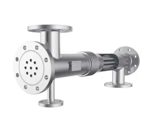
Shell and tube heat exchanger — Roffia srl

U-tube bundle

  • Thermal expansion: fully self-compensating
  • Bundle removal: yes (single tubesheet)
  • Tube cleaning: shell side only (mechanical)
  • Cost: lowest of all types
  • Best for: clean tube-side fluids, high pressure, large temperature differences

Fixed tubesheet

  • Thermal expansion: requires bellows if ΔT > 50–80 °C
  • Bundle removal: no
  • Tube cleaning: both sides (straight tubes)
  • Cost: low to medium
  • Best for: similar fluid temperatures, clean shell side

Floating head

  • Thermal expansion: fully compensating, no bellows
  • Bundle removal: yes
  • Tube cleaning: both sides (straight tubes)
  • Cost: highest
  • Best for: fouling fluids, large temperature differences, refinery service

Typical applications

Steam condensation

In turbine and process steam condensers, steam enters the shell side and is condensed by cooling water in the tubes. Correct condensate drainage via a steam trap or condensate pump prevents sub-cooling and flooding. Horizontal orientation is standard for gravity drainage. Titanium or stainless steel tubes are used where cooling water quality is poor.

Thermal oil heating

In industrial heating systems using thermal oil (diathermic oil) at 180–300 °C, shell-and-tube exchangers transfer heat to the process fluid. High shell-side temperatures and no phase change make this a standard fixed-tubesheet application. Carbon steel is adequate for most thermal oils; special coatings or stainless steel are used for highly oxidising thermal fluids.

Chemical and petrochemical processes

Refineries, petrochemical plants and chemical reactors rely on shell-and-tube exchangers for preheat trains, product coolers and heat integration. TEMA class R design with ASTM materials, ASME stamped, with full material traceability documentation. Special alloys (duplex, Hastelloy) are specified for hydrogen service, sour gas and acid environments where standard carbon steel fails rapidly.

High-pressure gas cooling

In biogas upgrading, compressed natural gas and industrial gas systems, the gas must be cooled after compression. Shell-and-tube exchangers handle the high tube-side pressure (50–300 bar) that would exceed plate exchanger limits. TEMA type X (cross-flow shell) minimises gas-side pressure drop, critical for aftercoolers where compressor energy efficiency is paramount.

Key sizing parameters

TEMA class

Class R for refinery and severe service; Class B for chemical process; Class C for general commercial. The class determines minimum wall thicknesses, tube-to-tubesheet joint requirements and testing standards.

Tube-side vs shell-side allocation

The more corrosive, fouling, higher-pressure or more hazardous fluid is usually placed on the tube side (easier to clean; smaller volume; easier to seal). Steam and cooling water typically go on the shell side unless fouling dictates otherwise.

Baffle design

Segmental baffles are most common. Baffle cut (20–45%) and spacing determine shell-side velocity and pressure drop. No-tubes-in-window (NTIW) baffles eliminate vibration in high-velocity gas applications.

Nozzle sizing

Inlet and outlet nozzles must be sized to limit erosion velocity and avoid impingement on tubes at the inlet — an impingement plate or distributor is added in high-velocity gas or steam inlet applications.

Domande frequenti

What are the main TEMA exchanger types and when do I choose each?
TEMA (Tubular Exchanger Manufacturers Association) classifies shell-and-tube exchangers by front end, shell type and rear end. The most common configurations are: Type E (one-pass shell, most common) — standard multi-pass tube arrangement; highest thermal efficiency for single-phase service. Type F (two-pass shell, longitudinal baffle) — achieves true counterflow in a single shell when the temperature cross would otherwise require two shells in series. Type J (divided-flow shell) — reduced shell-side pressure drop; suited to vacuum condensers and gas coolers. Type X (cross-flow shell) — very low pressure drop, used for gas and vapour applications. For rear-end type: U-tube bundles are the simplest and most economical — the bundle can be withdrawn without disturbing the shell, but tubes cannot be individually replaced. Fixed tubesheet is lowest cost but requires an expansion joint if the differential thermal expansion is significant. Floating head (types S, T, W) allows full bundle removal for cleaning; required for fouling tube-side fluids.
When is a shell-and-tube heat exchanger chosen over a plate exchanger?
Shell-and-tube exchangers are preferred over plate exchangers in four main scenarios. First, extreme operating conditions: pressures above 25–30 bar or temperatures above 185–200 °C exceed practical plate exchanger limits. Second, large temperature crosses: when the cold outlet must be hotter than the hot inlet, multi-shell arrangements are needed — shell-and-tube is well proven in this role. Third, fouling or corrosive fluids that would block plate channels: tube-side can be reamed mechanically; shell-side baffles create turbulence that plates cannot if the fluid carries solids. Fourth, high thermal duties: very large heat exchangers (above 5–10 MW) are almost always shell-and-tube because the plate frame becomes impractically large. A practical rule: if both a plate and a shell-and-tube unit can technically do the job, the plate will almost always be smaller, cheaper and more efficient — unless the conditions exclude it.
What materials are available for tubes and shell?
Tubes: Carbon steel (water, steam, non-corrosive service); stainless steel AISI 316L (general corrosive service, food and pharmaceutical); duplex stainless (chloride-containing water, seawater, oil field brines); titanium Grade 2 (seawater cooling, chlorine chemistry, aqueous acids); Hastelloy C-276 (strong acids, mixed acid service); admiralty brass (cooling water, condensers). Shell: Carbon steel (ASTM A516 Gr 70, standard); stainless steel 304/316 (food and pharmaceutical); for very aggressive shell-side fluids, clad (carbon steel + stainless cladding) or solid stainless. Material selection must be confirmed against the operating fluid composition, temperature and concentration — a compatibility chart or corrosion study is recommended for non-standard fluids. Roffia can advise on material selection for your specific duty.
How do shell-and-tube exchangers handle thermal expansion?
Differential thermal expansion between tubes (hot) and shell (cool, or vice versa) creates mechanical stress. The solution depends on the design type. U-tube bundles are the simplest answer: the U-bends absorb expansion freely, no mechanical stress. Suitable for clean tube-side fluids (the U-bends cannot be mechanically cleaned). Fixed tubesheet designs rigidly connect both tubesheets to the shell. Expansion is accommodated by an expansion bellows in the shell — required when ΔT (shell minus tube mean temperature) exceeds roughly 50–80 °C. Floating head designs allow one tubesheet to move axially relative to the shell — no bellows required, and full bundle withdrawal for cleaning. The floating head adds cost and requires careful sealing design. For large temperature differences in high-pressure service, floating head is the reliable solution.
What is the typical maintenance cycle for a shell-and-tube heat exchanger?
Shell-and-tube heat exchangers in clean service (boiler water, steam, filtered process water) can operate for 10–15 years without major intervention. In fouling or corrosive service, maintenance requirements are much more frequent. Typical activities: Annual — pressure test, visual external inspection for corrosion or erosion at nozzles and supports; review of operating data for performance degradation. Every 2–5 years — tube-side cleaning (hydraulic jetting or rodding for straight tubes, chemical cleaning for U-tubes), eddy-current testing of critical tubes (boiler feed heaters, condensers), gasket replacement if weeping occurs. Major overhaul — tube bundle replacement if tube wall thickness below minimum; retubing with upgraded alloy if original material no longer adequate. The Roffia technical team can advise on maintenance intervals and spare parts (gaskets, tubes, replacement bundles) for your exchanger.
Can shell-and-tube exchangers be used as condensers or reboilers?
Yes — they are the dominant technology for both duties. As a steam condenser: steam enters the shell side, cooling water flows in the tubes. Horizontal orientation allows condensate to drain by gravity; the lowest point carries a condensate drain to a steam trap or condensate pump. Sub-cooling of condensate on the shell side is undesirable (occupies heat transfer surface); proper condensate drainage via a steam trap is critical. As a reboiler (in distillation and evaporation): the exchanger heats the process fluid to its boiling point. Thermosiphon reboilers (natural circulation driven by density difference) are most common. The TEMA type is selected based on the boiling mechanism (nucleate or falling film) and whether the process requires a U-tube or floating head for differential expansion at the vapour-liquid interface.

Shell and tube heat exchanger enquiry

Tell us your operating conditions: fluids, temperatures, pressures, duty and TEMA class requirement. Our technical team will provide a design proposal and quotation.

Privacy Policy Cookie Policy